Prototype Building Process
The main components to be built and designed for the prototype are as follows:
-Receiver circuit board
-Transmitter circuit board
-Motor and mounting brackets and adaptors required
-Digital inputs connected to switches
The receiver circuit was developed, designed, and simulated by Catherine and Rezwana. A prototype of the circuit was built on a breadboard and fully tested and debugged before building a smaller soldered circuit on a circuit board. It was soldered and a voltage regulation circuit was built on so that it would be powered by a 9V battery. Figure 1 shows the receiver circuit board.
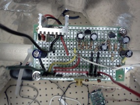
Figure 1: Receiver circuit board
The circuit board had to be mounted inside of the reflector in order to best make it directional. This was done with a dowel through the sides of the reflector, mounted with wood glue, as seen in Figure 2.
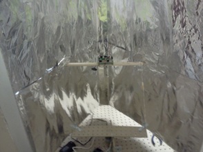
Figure 2: Receiver circuit board mounted inside reflector
The transmitter circuit was developed, designed, and simulated by Catherine and Rezwana. A prototype of the circuit was built on a breadboard and fully tested and debugged before building a smaller soldered circuit on a circuit board. It was soldered and a voltage regulation circuit was built on so that it would be powered by a 9V battery. Figure 3 shows the transmitter circuit board.
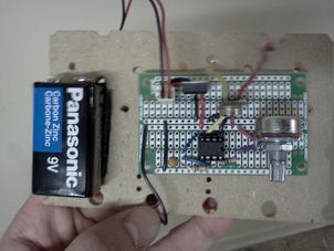
Figure 3: Transmitter circuit board
Various motors were tested with the prototype. Due to the nature of prototyping, the process used to select between various motors was one more targeted towards effectiveness than efficiency. We simply wanted to quickly find a motor that would work for this application and move forward. Because of long lead and shipping times, it was decided that instead of finding motors and ordering them on-line, it would be faster and more convenient to buy various motors from shops nearby and test them with the system. It was found that all of the stepper motors did not exhibit enough torque to rotate the reflector. A strong DC motor was found to rotate the reflector successfully. This motor had a D-shaft and came with an adaptor and a bracket. A mount was built to mount the motor onto the base weight and the adaptor was used to connect the shaft to the base of the reflector. The motor, adaptor, and mount are shown in Figure 4.
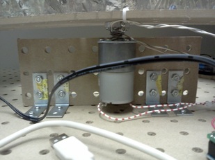
Figure 4: DC motor, adaptor, and mount
A method needed to be developed to control the software running on the Arduino. The best way to do this is to use the digital input pins that are available. The Arduino utilizes internal pull-up resistors, which means that a switch to ground will toggle the input from its normal state (high) to some new state (low). These inputs are thus active low. Pushbuttons were bought to use as switches and soldered onto a board for robustness. They can be seen in Figure 5.
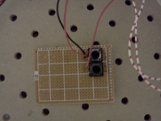
Figure 5: Pushbuttons for digital input to software